Oct 16, 2026
What Should Be Tested Before Final Assembly of an Electronic Collectible?
Test power, controls, LEDs, sound, movement and wiring before final assembly so electronic collectible faults remain visible and accessible.

Before final assembly, an electronic collectible should be tested as an accessible system: power input, switches and controls, LEDs, sound or mechanical functions, connectors and cable routing must all work in the intended sequence. Testing before the shell or base is closed keeps faults visible and allows a connection, component or fit problem to be corrected without disturbing finished surfaces.
The important distinction is between proving that individual parts can turn on and proving that the assembled subsystem behaves correctly in the product.
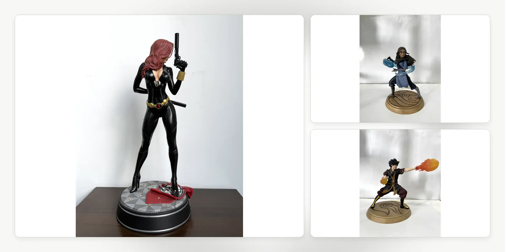
This real product image illustrates an illuminated effect. It does not document a test result or establish that the checks below have passed.
Test the subsystem before it becomes inaccessible
Bench-test electronic components first, then repeat the test after they are mounted in the prototype or production structure. A loose LED, speaker or motor may work by itself but behave differently once wiring is routed through narrow spaces and the part is held in its final position.
The test should use the intended power source, connectors and controls. Temporary connections can help diagnose a component, but they do not confirm the production assembly. Keep the housing open so that polarity, connector seating, wire movement and mechanical clearance remain visible.
Mancheng's functional collectible capabilities include LED, sound and mechanical features within resin, PVC/ABS and mixed-material products. The test plan should reflect the specific combination rather than applying one generic switch-on check.
Verify the complete power and control sequence
Start with the power path. Confirm that the input, battery compartment or power connector is accessible and secure in the intended assembly. Operate every switch, button and control in the sequence defined for the product, including start-up, mode changes and shutdown where applicable.
Look for intermittent behavior while the wiring is gently placed into its final route. A function that stops when the base plate moves may indicate a strained cable or poorly seated connector. The objective is to check the actual assembled path without pulling, pinching or sharply folding wires.
Check LEDs with the optical parts installed
An LED can illuminate correctly while the final effect still appears uneven. Test it with the diffuser, translucent casting, painted light-blocking areas and surrounding opaque parts in place. Check the principal viewing angles for dark zones, bright points and unintended light leakage.
This step separates an electrical pass from an appearance pass. A bright source is not automatically a successful effect if the light reveals internal hardware or breaks the intended finish. Optical adjustments should be resolved before the surrounding parts are permanently joined.
Test sound and movement under assembled conditions
Speakers, motors and mechanical features should be evaluated after mounting because the product structure can change their behavior. A speaker opening may be restricted by the housing. A moving feature may have adequate clearance before painting but contact a neighboring part after the finish and final hardware are added.
Run each function through its intended operating sequence while observing the mounting points and nearby decorative parts. Confirm that movement does not pull wiring, mark a surface or transfer force to a fragile element. If a mechanism depends on a removable panel, make sure that panel can be fitted without changing the function.
Secure routing before the assembly is closed
Once the functions pass, inspect the wire path and connections rather than closing the product immediately. Confirm that cables sit away from screw paths, sharp edges, moving parts and high-pressure joints. Connectors should remain reachable at the planned assembly stage and should not be held in position only by the outer shell.
Photographs or simple routing references are useful when the path is hidden after closure. They give assembly and QC teams a visible standard for connector orientation, cable placement and protected clearance.
These checkpoints belong in the development and production process, with hold points before any area becomes inaccessible.
Repeat a functional check after closure
Pre-closure testing is necessary, but it is not the final check. After the housing, figure or base is assembled, repeat the operating sequence and inspect the external result. Confirm that controls remain accessible, light and sound are unobstructed, movement has clearance and the surrounding finish is undamaged.
A useful test record identifies the product configuration, the functions checked and the stage at which they passed. It should distinguish a component test, a mounted-system test and a final assembled-product test. Teams defining a functional collectible can contact Mancheng with the intended effects and control sequence before the prototype structure is locked.
Frequently asked questions
Is testing each electronic component separately enough?
No. Individual tests find failed parts, but the mounted subsystem must also be checked with the intended power path, controls, connectors and routing.
When should an LED effect be approved?
Approve it with the final translucent, diffusing, painted and opaque parts in place so brightness, spread and light leakage can be judged together.
Should the functions be tested again after final assembly?
Yes. Repeat the complete sequence after closure to confirm that assembly has not restricted a control, connection, light path, speaker opening or moving feature.