How to Plan Part Breaks Before Tooling a Collectible
A practical engineering guide to planning part breaks around molding, painting, assembly strength, tolerances, QC and protective packaging.
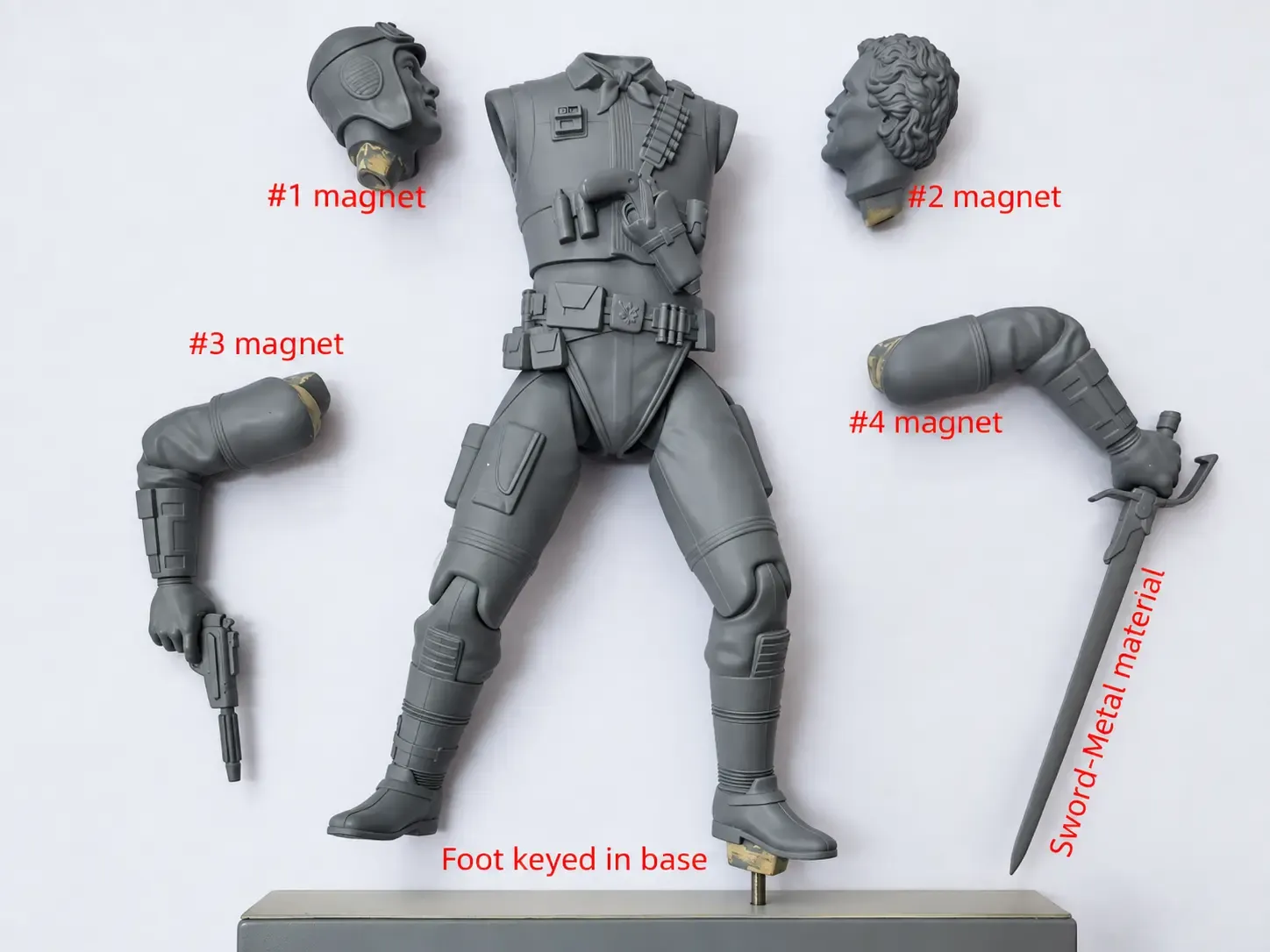
The practical answer: part breaks should be planned before tooling by reviewing the sculpt, production process, finish, assembly loads and packaging together. A good split is not simply where the 3D model is easiest to cut. It should make molding or casting reliable, give painters clear access, hide seams where possible, create strong repeatable joints and protect the product during shipment.
When these decisions are delayed until after the master is approved, the project often pays for them through visible seams, weak connections, difficult paint operations, tooling changes or avoidable rework.
What a Part Break Has to Achieve
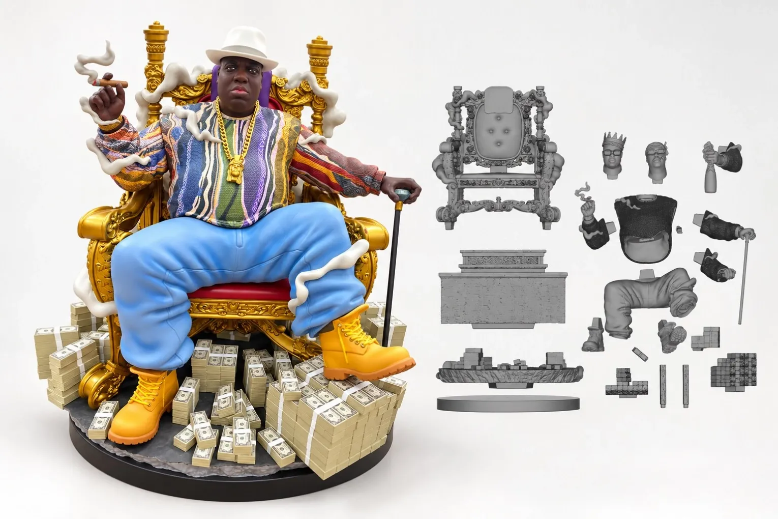
A production part break separates a collectible into components that can be tooled, molded or cast, finished, assembled and packed consistently. One break may solve several problems at once, but it can also create new ones. Moving a seam away from a face may improve appearance but make the mold more difficult. Combining two pieces may hide a joint but block paint access or increase breakage risk.
The correct solution balances the approved design with the actual production route. Resin statues, PVC/ABS figures, 1/6 articulated figures, mixed-material products and functional replicas each require different thinking.
Start With the Molding or Casting Route
Undercuts, deep recesses, long projections and trapped geometry are the first issues to review. A form that prints successfully as one piece may not release cleanly from a production mold. Thin features can also distort, trap air or become difficult to demold without damage.
Questions to resolve before tooling
- Can the part release from the intended mold without tearing the mold or damaging the casting?
- Are undercuts better handled by a separate component?
- Will gates, vents or mold lines fall on critical visible surfaces?
- Can the part be handled repeatedly without bending or breaking?
- Does the split create a practical tooling layout for the intended material and quantity?
For PVC/ABS components, draft, wall thickness, shrinkage and gate location influence the break strategy. For resin casting, mold access, air release, part weight and fragile projections require equal attention.
Protect the Sculpt Without Creating Obvious Seams
The visual objective is to place seams where the design can naturally absorb them. Clothing edges, armor panels, hair layers, belts, base transitions and hard material changes can provide useful boundaries. Faces, smooth skin areas and uninterrupted reflective surfaces are much less forgiving.
Seam concealment should never be treated as a cosmetic decision alone. If the joint cannot be assembled to the same depth and angle each time, even a well-placed seam will become visible in production. Key shape, insertion direction and tolerance must support the intended appearance.
Plan for Painting and Finishing Access
A component may be technically moldable but still difficult to paint. Brushes, spray guns, masks and inspection all require physical access. Deep folds, crossed limbs, accessories close to the body and layered costume elements can turn a simple paint specification into a slow and inconsistent operation.
Separating a piece can make skin tones, metallic coatings, translucent effects or clean color boundaries easier to control. However, more parts also mean more preparation, more paint fixtures, more assembly operations and more opportunities for mismatch. The decision should reduce total production risk rather than maximize part count.
Design Joints for Strength and Repeatability
A production joint needs more than matching surfaces. It must locate the component correctly, resist movement and tolerate normal variation in molded or cast parts. Heavy resin elements, extended weapons, effect pieces and large bases may require deeper keys, metal pins, screws, magnets or internal reinforcement.
Common joint risks
- A key is too shallow to control angle or rotation.
- A connection carries the weight of the part through a thin decorative area.
- Adhesive is expected to compensate for poor mechanical fit.
- Paint thickness reduces clearance at a tight joint.
- A joint can be forced into the wrong position during assembly.
Connections should be tested with the final material, surface preparation and finish—not only with clean 3D prints.
Account for Tolerances and Material Behavior
Digital files fit perfectly because they do not shrink, flex, accumulate paint or vary from mold to mold. Production parts do. Resin, PVC and ABS behave differently, and every joint needs realistic allowance for the chosen process.
Too little clearance causes incomplete assembly, scraped paint or excessive force. Too much clearance creates gaps and unstable alignment. The tolerance should be defined around the approved appearance and verified during prototype and sample development.
Our collectible development and production process connects engineering review, prototyping, tooling, finishing, assembly and QC so these interactions can be checked before volume production.
Review Packaging at the Same Time
Part breaks affect the package as much as the product. A removable weapon may reduce carton size and shipping risk, but only if the customer can install it safely. A preassembled fragile effect may look better out of the box but require a much larger protective tray.
Before tooling, review the likely tray orientation, pressure points, removable components and unpacking sequence. The strongest production design can still fail if the package transfers impact into a thin projection or heavy unsupported part.
A Practical Pre-Tooling Review
Before approving part breaks, review the complete assembly with representatives from sculpting, engineering, tooling, painting, assembly, QC and packaging. The review should confirm:
- Every component has a clear production method.
- Critical surfaces remain accessible for finishing and inspection.
- Joints locate parts consistently and carry the expected load.
- Tolerances account for material behavior and paint thickness.
- Seams are controlled against the approved visual standard.
- The product can be assembled, packed and unpacked without avoidable damage.
A small adjustment at this stage is usually easier than modifying tooling, repainting mismatched joints or rebuilding packaging after problems appear.
Frequently Asked Questions
Should a collectible use as few parts as possible?
No. Fewer parts can reduce assembly, but one-piece construction may make molding, painting or packing less reliable. The goal is the right number of parts for the product and production route.
Can part breaks be finalized from the 3D sculpt alone?
They should be reviewed on the 3D file, then verified through physical prototypes and sample assembly. Real materials, tolerances and paint layers often reveal issues that are not visible on screen.
When is it too late to change a part break?
Changes are still possible after tooling begins, but they can require tool modification, new tooling or repeated samples. The safest point to resolve the structure is before final tooling approval.
For an engineering review of an existing sculpt or prototype, send us your project scope with the target scale, materials, finish, quantity and functional requirements.